
The design of a structural glass wall is a methodical process, centered on matching the conceptual design as closely as possible, and then expanding to consider options for budget, materials, and schedule. The most common goal in the development of all-glass systems is to limit the design to the fewest number of components for the highest level of transparency possible.
While the design of truly custom wall systems is more costly than off-the-shelf systems, designers are freed up to avoid sizing and structural limitations that are often associated with pre-engineered products such as stick-built curtain wall.
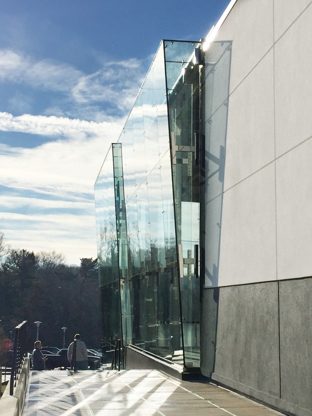
Our recently completed point supported structural glass wall at the Lord & Taylor store in Manhasset, New York is a good example to illustrate our process. The main entrance wall measures approximately 41’ tall by 130’ long, with an additional “display wall” measuring approximately 24’ tall by 16’ wide, for a total of 5,700 SF.

Structural Glass Wall Design Process
Bellwether begins its work with a high level feasibility analysis of the conceptual design, to determine basic appropriateness of design, availability of materials, etc. We evaluate the requirements of the wall system from the outside inward. Wall glass make-up is reviewed first based on proposed structural support, windloads, and any other criteria such as seismic, blast, and ballistic. We then move on to the options for the structural framing system, always keeping the focus on creating a system that is as simple and visually uncluttered as possible.
High Level Feasibility Analysis
This first stage reality check identifies any major issues that would make the project impractical or impossible to build. For instance, if the Lord & Taylor fins project had been designed to feature one-piece, 40’ tall glass fins, they would carry a huge cost, and make transportation and installation difficult and very expensive. These are import factors to consider if cost is a driving criteria!
Generally, at this stage, we are doing more of an exception-check on the design, rather than setting hard limits. We consider the ways to adapt the materials to the design, rather than boxing the architect in and making them adapt their design to the material limitations.
Analysis of Wall Glass Materials
The appropriate make-up of wall glass is defined by factors ranging from the size of the largest glass lites, to the type and frequency of glass anchorage (e.g. point supports vs. patch fittings, vs. continuous two-sided structural silicone support), local windloads, etc. In the case of Lord & Taylor:
- Wall lites are large, with the largest measuring 10’-11 3/4” wide X 10’-4” tall.
- At over 113’ SF each, and over 1,800 pounds each, these are much larger than what is found in most point supported applications.
- The specified glass was a laminated make-up, with a thickness to be confirmed by the supplier.
- Glass thickness is often a function of limiting deflection due to wind loads. Wind loads are relatively high at the Manhasset site, at 111 MPH. We used a 1-1/16” thick make-up, utilizing two layers of 1/2” glass, with a .060 PVB interlayer.
- The conceptual design for the wall assumed just four fittings per lite of glass, with one at each corner. This was one area where we knew that the design would have to be adjusted from the start. The inclusion of a mid-span support along the 10’-4” span on the sides of each lite (for a total of six fittings per lite) was assumed to manage glass deflection. This addition of the mid-span fitting had a minimal impact on the overall aesthetic or cost.
Analysis of Glass Wall Backup Structure
The determination of the appropriate material depth, thickness, and hardware for a glass fin wall is determined by a number of standard factors, such as height of the wall, width of bays and whether the wall is hung from above, or dead loaded to the ground. In this case, due to the depth of the fins to allow for the inverted wall, the requirement to limit buckling of the fins also became the critical factor in their design.
- The height of the wall would require deep and thick fins. At 40’ tall, these are massive structural components, regardless of material.
- The depth of the fins were somewhat determined by:
- The 2’ dimension at the base, which was driven by a desire to maximize retail floor space.
- The degree of inversion at the head condition. We reviewed 3 degrees, 4 degrees and 5 degrees, ultimately setline on 4 degrees for engineering efficiency.
Since these dimensions were relatively settled, we evaluated the required thickness of fin glass to manage deflection and buckling. This turned out to be 2-3/8”, made up of 3 layers of 3/4” glass, with two .060 SGP interlayers.
- The fins are designed in 4 pieces, with the top components weigh over 1,100 lbs. each.
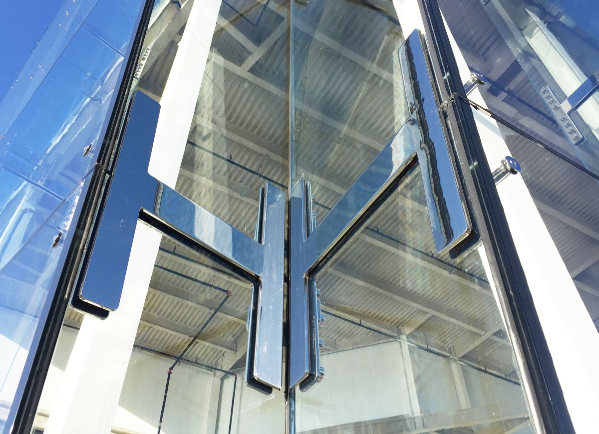
- The combination of high windloads, wide bay widths and a 40’ span introduced a need to address the potential for buckling of the fins under load. Bellwether addressed the concern through the use of the triple laminated/SGP make-ups, and splice plates that were designed in modified “H” shapes to greatly enhance stability.

Point Supported Wall Fitting Analysis
Fitting requirements on any point supported project are based on criteria such as articulation of the fitting head, bearing area (or glass bite), of the fitting head on the glass, and distance between fittings, as related to the thickness/stiffness of glass.
- Disk style fittings were the selected from the start, to provide far greater bearing area than countersunk fittings – especially important with lites of this size.
- The H shaped splice plates were developed and proposed by Bellwether during the design and engineering phase. Additional stainless straps were incorporated into splice plate design at the inverted corner, to manage deflection and buckling at this unique condition.

As with every custom project, the requirements of the base building design, and site specific environmental conditions like high wind loads, created some unexpected challenges along the way, changing material thickness and component design strategy. Bellwether’s approach through the process was to keep the project as closely centered on the architect’s original design concept as possible, with a high level of customized design and coordinated engineering.
The result is a stunning entrance with massive glass components, which completely transforms the entrance to Lord & Taylor’s flagship store, to celebrate its 75th anniversary.
Glass Magazine Award Winner
We were beyond pleased to have the Lord & Taylor project selected by Glass Magazine as the recipient of the 2017 Most Innovative Curtain Wall Project. Glass Magazine awards are given to projects that feature bold feats of glass and glazing innovation, fabrication, installation, and design. This was Bellwether’s second time winning the award for Most Innovative Curtain Wall, having first won the award in 2014 for our Hyatt Place Crinkle Wall project.

Credits
Architect: Highland Associates, New York, NY
Installer: Craftsman Storefronts & Glass, Inc., Bayshore, NY
General Contractor: EW Howell, New York, NY